This year I decided to ride the Dunwich Dynamo, having done it once before in 2012. For those of you not in the know, it is a 186km ride from London Fields in Hackney, out to the Suffolk coastal town/village of Dunwich, done (mostly) overnight. It’s a relaxed, friendly affair - definitely not a race, and the light-hearted nature of the event attracts a wide range of people and bikes. Included in this last category is the increasing number of people who choose to illuminate their bike in some way. When I last rode in the event I saw a guy with fairly lights on this bike, and thought that was pretty cool. In the week leading up to this years event I recalled seeing that guy’s bike, and fresh off the back of the Dance Floor project, I decided that I would do something to bike.
First, a word about my bike - unlike most people on the ride, I had a mountain bike. Don’t get me wrong, there are always a vast array of bikes on display, from carbon road bikes, recumbents, Bromptons to Eliptigo bikes, but we, in the non-road bike camp, were definitely in the minority. My bike is about 5 years old, and I’m not over-protective of it, so didn’t think twice about the possibly of taping many LEDs to it. None of what I’ve done is permanent, but once everything is removed it will probably be just as much work to put it all back as the first time I did it.
Here’s a sneak preview of what my bike will look like during the day, and at night:
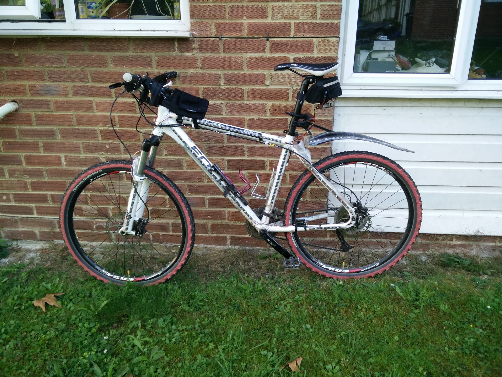 In the daytime
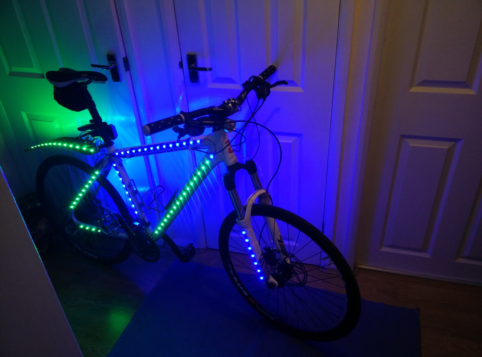
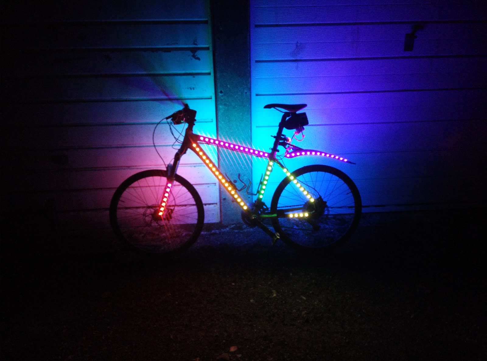 At night
Ingredients: 1x 5m reel of WS2812b addressable LEDs 30/m (sometimes marketed as ‘Neopixels’) 1x Arduino (Due in this case, but anything that runs at 5v would do) 1x 11.1v 2200maH Lipo battery 1x 12>5v 10amp DC/DC converter
- Wire, Solder, tape
I started with the LEDs: I bought these on eBay some time previously, and hadn’t got around to using yet. I had a 5m long strip, where the surface mount LEDs are soldered to a flexible backing, with 30 LEDs per metre.
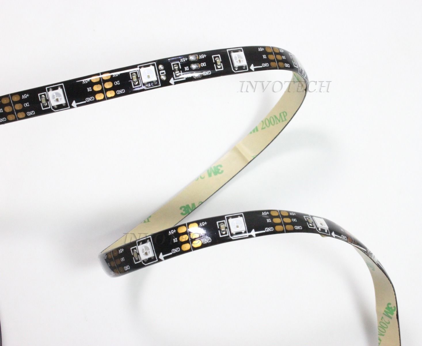
I ordered them from an eBay seller in China, costing me £24. (I’ve had overwhelmingly positive experiences with sellers in China / HK / etc, but your mileage may of course vary). Naturally they took a few weeks to arrive, so it was useful that I had these lying around for my last minute project.
Next, I needed to check they were working, so I brought up a quick Arduino sample sketch from Adafruit’s Neopixel library. Knowing that these LEDs are rated at 9W/m, I was wary about running them all from my computers USB port (normally only rated up to 500ma), so I changed the ‘strandtest’ example sketch to only display a limited number of pixels:
 Looks good!
Next I had a think about how I would go about arranging these 150 LEDs around my bike to get the best coverage and also how to go about wiring them - naturally I wanted to get as many as possible onto the bike.
First it made sense to think about where on the bike the Arduino, voltage converter, and the battery/batteries would go - my saddlebag was the obvious place to store the batteries, so I started there. A note about Lipo batteries - they don’t particularly like getting damaged, so I was reluctant to expose them to the elements. The saddle bag gave me the option of putting multiple batteries in there, as well as them being easily removable for charging, and I could also wrap them in some padding if I was concerned for their safety. After the battery, it made sense for the voltage converter to be close, as well as the Arduino, so I decided to cable-tie the converter under my saddle bag, and the Arduino would be attached to the frame somewhere in the vicinity. Here is what I came up with:
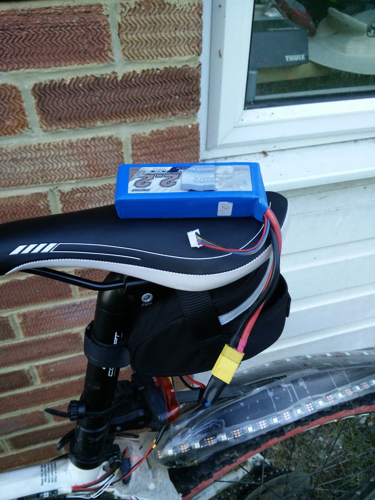 2.2 Amp Hour Lipo Battery. One of two I have, so both were stashed together in the saddle bag
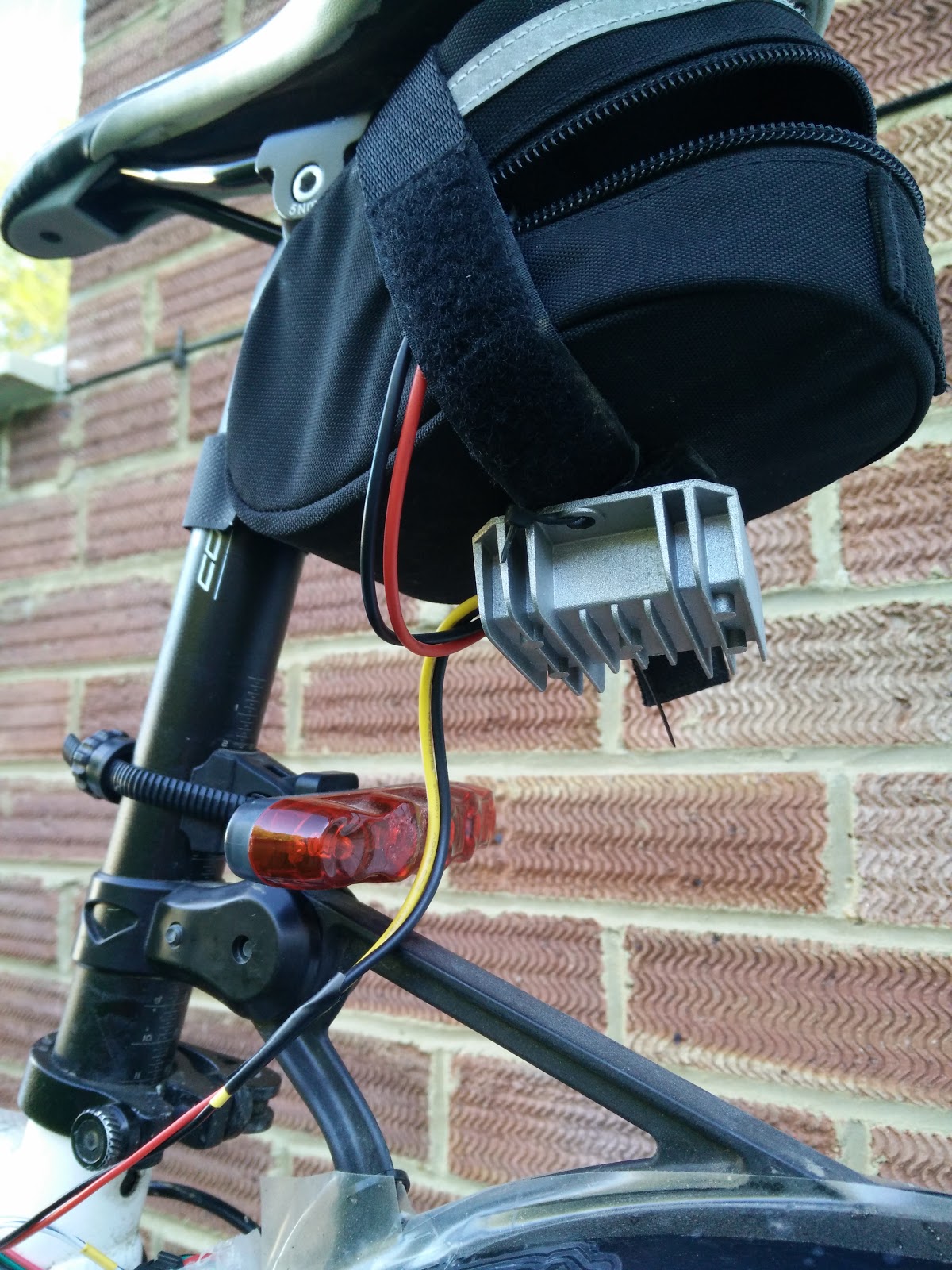 The 12/24 > 5v 10amp converter (another eBay purchase I had lying around) was cable tied under the saddle bag.
 The Arduino, nestled in some bubble wrap, attached with some more cable ties, and also some tape.
Next, the wiring of the LEDs, a nice little puzzle to solve - how to route a single string of LEDs around the bike minimising doubling-back and thus having to use lots of extra wire. The good news is, that starting at the base of the saddle stem you can go all around both sides of the bike, covering all the major frame pieces, as well as the rear mudguard with minimal doubling back (on the front-forks only) ! Here’s a diagram to explain the ordering, starting from the red dot by the saddle:
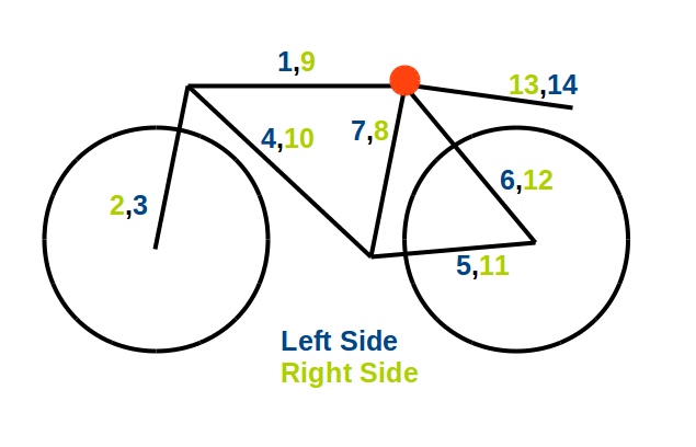
I cut the reel of LEDs into appropriate length strips to fit each frame section, with one eye on the total number of LEDs available so as to share them out evenly. The strips cut easily with a pair of scissors, so this bit was a doddle. I taped each of these sections of LEDs to the appropriate parts of the frame. I used regular selotape in a few places to make sure they would stay in place, but I wasn’t too concerned about using an excessive amount because I was planning on covering everything in a much wider clear tape at the end in order to provide some amount of protection against dirt and moisture I soldered the data cable from the end of one section to the beginning of the next according to the diagram above, having made sure that the LEDs were correctly oriented when they were first attached (they have an IN and an OUT) - I used white wire for this. Finally I soldered the 5v and ground wires up with red and black wire respectively. In order to avoid a large voltage drop at the very end of the string of LEDs I joined a number of sections from both sides of the bike together at junctions where they all coincided, such as at the crank and up by the handlebars.
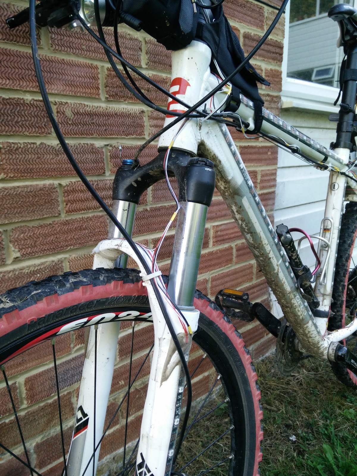 The forks were the only place where extra wire needed to be used because each legs of the fork is effectively a dead end - I had to bring the data cable back up on each side
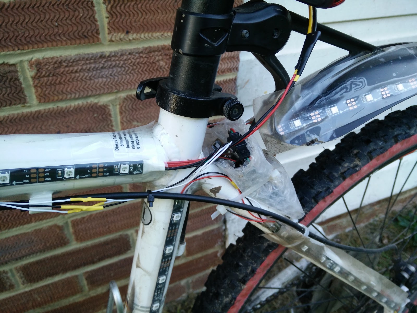
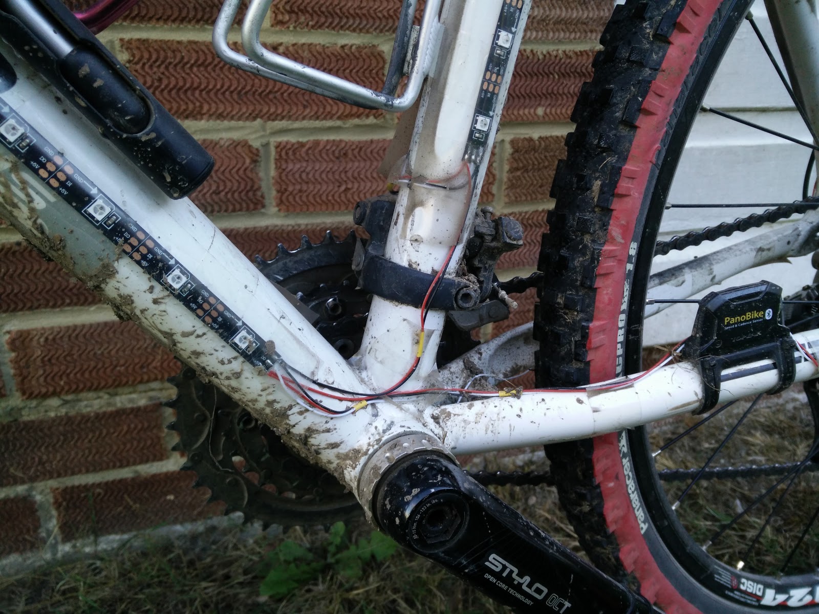 Here you can see that the data cable (white) goes down the bottom tube and heads towards the back wheel, but I’ve joined all 3 (in fact 6) pairs of 0v/5v cables together to even the voltage
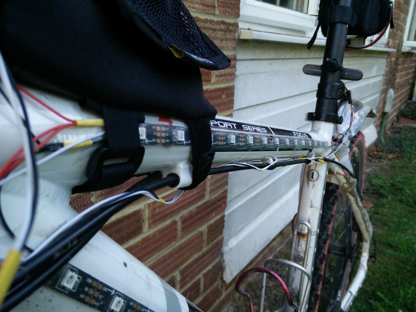 I tried to be as neat as possible, using heat-shrink tubing everywhere (yellow)
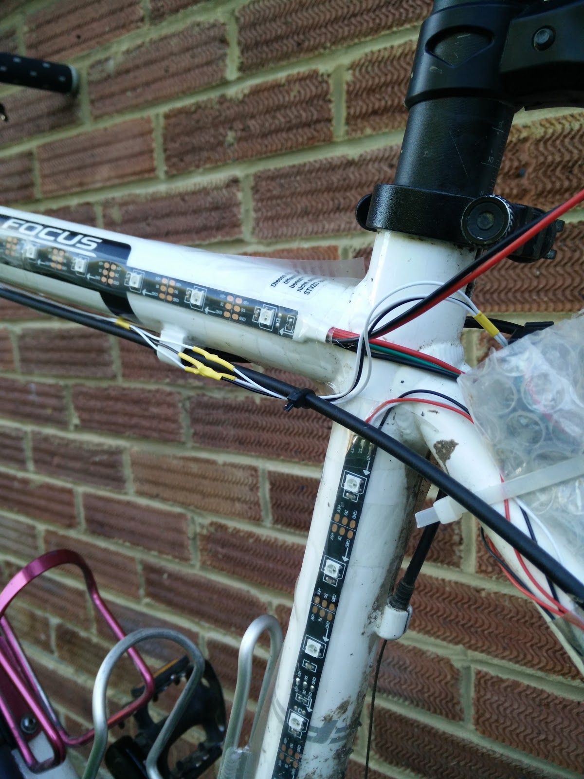 It was a bit busy around the seat post with power from the battery coming down to the Arduino as well.
The last bit of wiring was to take a switch up to the handlebars so that I could turn the lights on and off, or more importantly, change the pattern that was on display. I had a two way, centre off, momentary switch lying around, so I used that. When it came to it I only used one side of the switch, which simply toggled through the different visualisations with each press
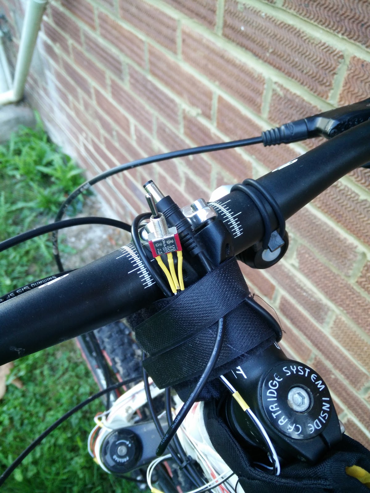 Handily, my main bike like battery was velcro’ed on here, so it provided a convenient way to attach it in an accessible place
Finally, all that remained was the firmware for the Arduino! I had spent two evenings on the project by this point, so there wasn’t a lot of time to throw the code together, but the heavy lifting was done by the Adafruit library, so when it came to it the test code took all of a couple of minutes to get going.
In order to display some more interesting bike shaped patterns I had in my head I needed to work out the position of each LED and it was this that ended up taking most of the rest of the second day of construction - I fancied having a strobing effect running from front to back, so I wrestled with arrays and offsets of each strip for a good while before things came out looking right.
I have put the code up on github for anyone else that fancies taking it and either running it as is, or extending it. The code is originally based off the ‘strandtest’ sketch in Adafruit’s Neopixel library.
In the end I had a number of visualisations I could select between: Off - useful during the daylight hours Road Mode - the front forks were white, the rear mudguard all red Rainbow 1 - The full colour wheel was visible across the entire bike Rainbow 2 - A moving window of the colour wheel was visible, which caused the bike to have a general hue of e.g. green, before seamlessly drifting into red, blue and back around again. Strobe - Lights flashed from front to back Disco Mode - All LEDs were one of the combinations of Red/Green/Blue excluding black and white, giving us 6 really bright colours. I did a few back of the envelope calculations based on what my bench power supply said the current draw was for each of these options, and it was clear that Disco Mode was the most battery hungry (every pixel was full on for at least one of R/G/B). All said, I thought maybe I’d be able to get a couple of hours out of each of my two batteries. In the end I think it was probably closer to 3 hours total, but I think I may have used the more power hungry ones for longer than intended.
Improvements to be made: Provide a mechanism to dim the LEDs. They don’t need to be on full brightness all the time, which would help extend battery life considerably Make the switch work a bit better. It seems unresponsive at times, which could be a software problem, or it might be a break in the wire somewhere!
Overall it was a big success and I got a lot of complements from other riders, and it made me happy to hear that it cheered people up during the small hours of the night. The batteries lasted well enough, but power conservation will definitely help for next time.